Technical Guides
Home << News << Technical Guides << Excavator Tiltrotators and Large Tilt Buckets: Why Buckets Drift and How to Prevent ItExcavator tiltrotators and rotating tilt buckets can significantly improve grading, ditching, slope shaping, landscaping, river maintenance and utility work. Instead of repeatedly repositioning the excavator, the operator can change the attachment angle directly from the cab.
For smaller machines, this flexibility is relatively easy to manage. On a 30–40 tonne excavator equipped with a large grading or tilting bucket, however, attachment weight, bucket width and the distance between the cutting edge and the tilt pivot create much higher loads.
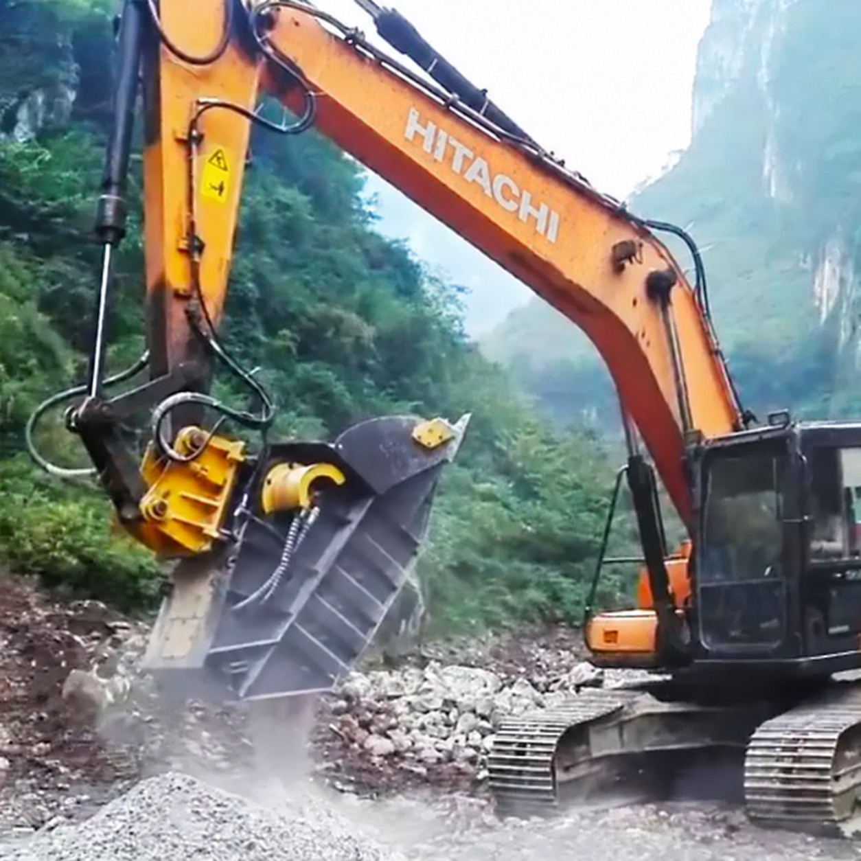
Large excavator operating with a heavy-duty rotating tilt bucket at a high working angle.
This is why some operators experience a common problem with large tilt buckets: after the bucket is tilted toward its working limit, it slowly moves away from the commanded angle even though the control joystick has returned to neutral.
This behavior is often called bucket drift, tilt drift or hydraulic creep.
The solution is not as simple as installing a larger cylinder, increasing hydraulic pressure or adding a worm gearbox. To diagnose the problem correctly, the hydraulic circuit, mechanical transmission, load-holding system, pins, bushings and attachment geometry all need to be considered.
This guide explains how these systems work, why large tilt buckets can drift, what worm-gear self-locking actually means, how pressure and flow should be matched, and what buyers should verify before installing a heavy-duty tilt attachment.
These terms are often mixed together in attachment marketing, but they describe different systems.
A tilt bucket has its own hydraulic tilting mechanism. The bucket can move from side to side, but it normally cannot continuously rotate around the excavator arm.
A tilt coupler is installed between the excavator stick and the attachment. Instead of allowing only one bucket to tilt, it allows compatible work tools to be tilted.
Some tilt couplers provide very large total tilt ranges, including designs approaching 180 degrees of total movement.
A tiltrotator combines continuous rotation with side-to-side tilting. A common industry configuration is approximately 360-degree continuous rotation with about 40–50 degrees of tilt in each direction.
For example, Steelwrist specifies 360-degree rotation and 45-degree tilt in each direction across much of its tiltrotator range. Rototilt also publishes tiltrotators with similar working principles, although exact angles depend on the model.
See the manufacturer's specifications at Steelwrist Tiltrotators and Rototilt Tiltrotators.
This distinction is important when troubleshooting drift because the rotation mechanism and the tilt mechanism may use completely different components.
Bucket drift rarely has one universal cause. It can result from hydraulic leakage, insufficient load holding, mechanical clearance, valve behavior or attachment geometry.
A heavy bucket does more than add weight.
As the distance between the bucket's center of gravity and the tilt pivot increases, the load generates greater torque around the tilt mechanism. The effect becomes especially noticeable when the bucket is wide, heavily loaded or operating near its maximum tilt angle.
This means two buckets with the same hydraulic cylinder can behave very differently.
A smaller attachment may appear perfectly stable even when a small amount of internal hydraulic leakage exists. Install a much heavier grading bucket and that same leakage may become visible as slow bucket movement.
This is one reason attachment compatibility should never be determined from excavator tonnage alone.
A hydraulic cylinder can lose position without leaking oil externally.
If piston seals wear, hydraulic oil can bypass internally from the pressurized chamber to the opposite side of the piston. Under sustained load, even a relatively small amount of internal leakage can allow the cylinder to move gradually.
The heavier the attachment and the longer the lever arm, the more visible the movement becomes at the cutting edge.
The directional control valve must also maintain the position of the actuator when the operator releases the control.
Internal valve clearances, spool wear, contamination or damage can allow oil to migrate through the circuit under load.
If troubleshooting points toward valve behavior rather than the cylinder itself, the broader excavator hydraulic control system should also be inspected. Topvelsun's excavator hydraulic valves section provides examples of directional, pressure, flow and electro-hydraulic control components used in excavator systems.
Large tilt attachments should not rely only on the neutral position of the main directional valve to hold a heavy load.
Depending on the design, pilot-operated check valves, counterbalance valves or dedicated load-holding valves can be used to prevent the load from driving the actuator when no movement is commanded.
Parker explains that a counterbalance valve can hold a load when control pressure is removed and control the descent of an overrunning load. See Parker's counterbalance valve technical information.
Rototilt takes a similar approach on its tiltrotators. The company specifies built-in load-holding valves on its double-acting tilt cylinders and states that the system is intended to secure the load if hydraulic pressure is lost, including situations such as a hose rupture. See Rototilt's tiltrotator design information.
This approach is also consistent with the broader principles in ISO 4413:2010 — Hydraulic fluid power — General rules and safety requirements for systems and their components.
Therefore, one of the most important questions when evaluating a heavy tilt attachment is not simply:
“How large are the cylinders?”
It is:
“How is the load held when hydraulic control returns to neutral or pressure is unexpectedly lost?”
Not every moving cutting edge indicates a hydraulic problem.
Wear in pins, bushings, coupler interfaces and pivot joints can create mechanical backlash.
A relatively small clearance near the pivot can become much more visible at the cutting edge of a two-meter-wide bucket.
Before adjusting hydraulic pressure, technicians should determine whether the cylinder itself is moving or whether the movement is occurring through mechanical clearance.
This is one of the areas where attachment marketing can become misleading.
A worm-and-wheel gearbox can be designed so that the worm drives the wheel but the wheel has difficulty driving the worm backward. This behavior is generally referred to as self-locking or resistance to back-driving.
However, a worm gearbox is not automatically self-locking simply because it contains a worm and wheel.
KHK, a specialist gear manufacturer, explains that worm-gear self-locking depends on multiple factors including lead angle, friction, material, machining accuracy, bearing characteristics and lubrication. KHK specifically recommends using an additional braking mechanism when complete prevention of reverse motion is required.
See KHK's technical reference on worm-gear self-locking.
Even when a worm gearbox has strong resistance to back-driving, it only affects the axis that the gearbox controls.
This distinction is extremely important on tiltrotators.
Some tiltrotators use hydraulic cylinders for side-to-side tilting while the rotation mechanism uses a worm gearbox.
KINSHOFER, for example, specifies an oil-bath worm drive for the rotational movement of its TR025 tiltrotator. See KINSHOFER TR025 technical information.
Rototilt also describes the worm gear operating inside its oil-filled rotor housing.
Therefore, if a bucket is drifting sideways around the tilt axis while the rotation axis remains stationary, modifying the worm gearbox in the rotation mechanism may not solve the problem at all.
The technician should instead inspect the tilt cylinders, load-holding valves, hydraulic control circuit and mechanical pivot points.
Even when a worm-drive system is intentionally designed for self-locking behavior, it should not automatically be treated as the only safety mechanism for holding a heavy excavator attachment.
Lubrication condition, wear, vibration, shock loading and changes in friction can affect reverse-driving behavior.
For heavy construction machinery, a more robust engineering approach is to combine appropriate mechanical resistance with hydraulic load holding and suitable structural capacity.
A properly engineered system may therefore include:
appropriately designed worm or reduction gearing where required;
load-holding or counterbalance valves;
correctly sized cylinders;
low-leakage hydraulic components;
adequately sized pins and bushings;
rigid structural geometry;
correct operating pressure and flow;
regular inspection and lubrication.
A larger cylinder bore can produce more theoretical hydraulic force at the same pressure because hydraulic force is determined primarily by pressure multiplied by effective piston area.
This is a legitimate reason for using large-bore cylinders on heavy tilt attachments.
However, a 100 mm cylinder does not automatically mean faster movement or better hydraulic flow.
A larger cylinder also requires more oil volume to travel through the same stroke.
Therefore, cylinder bore must be evaluated together with:
rod diameter;
stroke;
mounting geometry;
working pressure;
available hydraulic flow;
hose diameter;
valve capacity;
desired operating speed.
If the host excavator cannot provide sufficient auxiliary flow, installing a larger cylinder can actually make the tilt function slower.
For more background on the relationship between hydraulic flow, displacement and pressure, see Topvelsun's hydraulic pump pressure and flow buying guide.
No.
Some large rotating attachments use two hydraulic motors, and a correctly engineered dual-motor system can provide substantial rotational performance.
But the number of motors alone does not determine output torque.
Actual rotation torque depends on factors including motor displacement, pressure differential, mechanical efficiency and gearbox reduction ratio.
Dual motors can also increase hydraulic flow demand.
For this reason, buyers should compare actual specifications such as rated turning torque, maximum pressure, recommended flow and rotation speed rather than relying only on phrases such as “dual motor” or “high torque.”
The same basic hydraulic principles apply to other excavator rotary systems. Topvelsun's excavator hydraulic swing motors section provides additional context on hydraulic rotary drives, braking and swing-related failure symptoms.
One of the most important installation mistakes to avoid is assuming that every tiltrotator designed for a 35-tonne excavator should use the same pressure and flow settings.
There is no universal “35-ton excavator tiltrotator pressure” or “standard 35-ton tiltrotator flow rate.”
Different products use different hydraulic circuits, motor displacement, control valves, cylinder geometry and internal pressure compensation.
A useful real-world comparison is the Rototilt RC9.
The RC9 is designed for excavators between approximately 32 and 43 tonnes. Rototilt publishes the following specifications for the current RC9:
machine weight range: 32,000–43,000 kg;
maximum bucket width: 2,400 mm;
maximum breakout force: 280 kN;
maximum breakout torque: 500 kNm;
tilt angle: 2 × 40 degrees;
working pressure: 35 MPa;
recommended hydraulic flow: 206 L/min;
rotation torque: 19,100 Nm;
double-acting cylinder tilt torque: 90,000 Nm.
See the current Rototilt RC9 technical specification.
Those figures are very different from another heavy-duty rotating tilt bucket that may use separate low-flow circuits for rotation and tilt.
This does not mean one specification is correct and the other is incorrect. It demonstrates why hydraulic parameters must be treated as attachment-specific.
The following values represent one heavy-duty rotating tilt bucket configuration and should not be treated as universal settings for every 35-tonne excavator.
| Item | Example Specification |
|---|---|
| Recommended excavator class | Approximately 35 tonnes |
| Attachment weight | Approximately 2,035 kg |
| Approximate overall dimensions | 2,000 × 2,200 × 1,000 mm |
| Tilt angle | Up to approximately 45° per side, depending on configuration |
| Tilt working pressure | 20–25 MPa |
| Tilt recommended flow | 70–80 L/min |
| Rotation working pressure | 10–12 MPa |
| Rotation recommended flow | 35–50 L/min |
| Tilt mechanism | Dual large-bore hydraulic cylinders |
| Rotation drive | Dual hydraulic motor configuration |
Before installation, these values must be checked against the actual excavator auxiliary hydraulic circuit, hose dimensions, control-valve capacity, coupler configuration and attachment manufacturer's instructions.
Topvelsun's broader excavator hydraulic system parts section provides additional context on the pumps, valves, motors, seals, hoses and other components involved in excavator hydraulic systems.
The cutting edge and lower wear surfaces of a large grading bucket experience continuous abrasive contact with soil, sand, gravel and other materials.
Using a replaceable wear edge can reduce repair time because the worn section can be replaced without rebuilding the complete bucket body.
NM400-type wear plate belongs to the general approximately 400 HBW wear-resistant steel class.
For an internationally documented comparison, SSAB specifies Hardox 400 with a nominal hardness of approximately 400 HBW and a published hardness range of 370–430 HBW for plate.
See the official SSAB Hardox 400 specification.
This does not mean NM400 and Hardox 400 are automatically identical materials.
If a manufacturer claims that a bucket uses NM400, Hardox or another specific wear-resistant steel, professional buyers should request the actual mill certificate or material certificate for the supplied plate.
42CrMo alloy steel is widely used for highly stressed mechanical components because suitable heat treatment can provide a useful combination of strength and toughness.
It can therefore be a reasonable material choice for heavily loaded attachment pins.
However, writing “42CrMo pin” on a specification sheet does not by itself guarantee long life.
Pin durability also depends on heat-treatment condition, surface hardness, dimensional tolerance, bushing material, surface finish, lubrication and sealing.
For a heavy tilt bucket, these manufacturing details can be more important than the material name alone.
Claims such as “permanently zero clearance” should also be avoided. Pin-and-bushing joints require controlled working clearance. The objective is to minimize excessive play while maintaining proper motion and lubrication.
Property class 12.9 is a recognized high-strength fastener classification rather than simply a marketing description.
The relevant international standard is ISO 898-1 — Mechanical properties of fasteners made of carbon steel and alloy steel.
However, high bolt strength does not automatically prevent a joint from loosening under repeated vibration.
Joint design, bolt preload, tightening procedure, contact surfaces and any required locking method remain important.
Zinc-flake coatings are mainly used to improve corrosion protection.
For steel fasteners, the relevant international reference is ISO 10683:2018 — Fasteners — Non-electrolytically applied zinc flake coating systems.
ISO 10683 also notes the suitability of these coating systems for high-strength fasteners where reducing the risk of internal hydrogen embrittlement is important.
A zinc-flake coating should therefore be described primarily as a corrosion-protection treatment.
It should not be marketed as proof that a bolt cannot loosen under vibration.
A large tiltrotator or rotating tilt bucket adds weight at the end of the excavator arm.
It may also increase the distance between the original bucket pin and the cutting edge.
This changes leverage throughout the digging geometry.
Possible consequences include reduced effective breakout performance, increased pin and bushing loads, changes in lifting capacity, greater structural stress and changes in machine stability at long reach.
This is another reason buyers should not choose an attachment using excavator operating weight alone.
Large tiltrotator manufacturers commonly specify additional limits such as maximum bucket width, breakout force and breakout torque.
Rototilt's RC9 specification, for example, provides limits for machine weight, bucket width, breakout force and breakout torque rather than relying on machine tonnage alone.
The primary productivity advantage of a tiltrotator is not necessarily that the excavator digs faster during every individual bucket cycle.
The larger advantage is reducing movements that do not directly produce finished work.
With rotation and tilt available at the attachment, an operator can often:
grade a slope without repeatedly repositioning the tracks;
clean different sides of a ditch from one machine position;
shape road shoulders and drainage profiles;
work around pipes and utility lines;
grade close to walls and foundations;
perform landscaping and finishing work;
shape riverbanks and canals;
handle materials from more useful approach angles;
reduce manual finishing work around the excavator.
Steelwrist describes the same basic productivity mechanism: 360-degree rotation combined with side-to-side tilt allows the operator to perform more work without repositioning the excavator.
See Steelwrist's tiltrotator application overview.
The additional flexibility comes with trade-offs.
A tiltrotator adds weight and installation height between the excavator stick and the bucket.
For high-volume bulk excavation, very narrow deep trenching or tasks where maximum breakout performance is more important than attachment flexibility, a direct-mounted bucket may sometimes be the better configuration.
This is why modern fully automatic coupler systems increasingly allow operators to remove the tiltrotator when it is not required.
Automatic hydraulic connection systems can further reduce downtime by allowing compatible hydraulic attachments to be connected from the cab.
Engcon's EC-Oil is one example. The system combines hydraulic connections with compatible quick couplers so operators can change hydraulic attachments without manually connecting hoses.
Other manufacturers use their own systems and terminology.
Quick coupler safety should be evaluated separately from attachment-change speed.
The relevant international safety reference is ISO 13031:2016 — Earth-moving machinery — Quick couplers — Safety.
ISO also published ISO 13031:2016/Amd 1:2025 in February 2025.
For buyers, this means quick-coupler evaluation should include locking design, indication or monitoring functions, attachment compatibility and manufacturer instructions rather than focusing only on how quickly the coupler opens and closes.
Modern tiltrotators increasingly integrate hydraulic hardware with electronic control.
Proportional control allows tilt and rotation speed to be modulated smoothly instead of behaving as simple on/off functions.
This is particularly valuable during finish grading and precision positioning.
Position sensors can also allow tilt and rotation information to be shared with compatible machine-control systems.
These systems may assist the operator in maintaining target grades, slopes or attachment orientation.
Control-system names should not be treated as generic industry standards.
For example, DC2 and DC3 are engcon control-system families. Engcon currently describes DC3 as its newer proportional control platform integrating hydraulics, electronics and software.
See engcon's current control-system information.
Inspect the tilt circuit first.
Potential causes include cylinder internal leakage, control-valve leakage, load-holding valve problems, incorrect counterbalance settings, damaged hoses or fittings, and excessive mechanical clearance.
Inspect the rotation circuit and rotation transmission.
Depending on the design, this can include hydraulic motors, directional valves, gearbox wear, worm-drive condition, bearings and any dedicated holding or braking mechanism.
Inspect pins, bushings, attachment interfaces and coupler joints for mechanical play.
Separating these three conditions prevents a common diagnostic mistake: attempting to correct hydraulic tilt drift by modifying the rotation gearbox.
Modern excavator hydraulic systems use high-precision pumps, motors and control valves with small working clearances.
Contamination can accelerate wear, damage sealing surfaces and increase internal leakage.
Incorrect viscosity can also affect leakage, lubrication and heat generation.
The excavator's main hydraulic pump provides the pressure and flow required by working functions and auxiliary circuits, so overall hydraulic condition can influence attachment performance.
For a more detailed explanation of excavator piston-pump design and hydraulic efficiency, see Topvelsun's radial vs axial piston pump guide for excavators.
A heavy attachment operating at the end of a large excavator experiences substantial cyclic loading. Small problems can develop into expensive failures if they are not identified early.
Routine inspection should include hydraulic hoses, external leakage, cylinder drift, load-holding behavior, gearbox lubrication, pins, bushings, fasteners, cutting edges, coupler locking components, welds and structural plates.
Worm-drive lubrication is particularly important because worm gearing produces considerable sliding contact and heat.
Rototilt specifically identifies lubrication and heat dissipation as advantages of its oil-filled rotor housing design.
exact excavator make and model;
machine operating weight;
boom and stick configuration;
machine serial number where required;
maximum breakout force;
maximum breakout torque;
attachment weight;
bucket width;
bucket capacity;
center-of-gravity position;
tilt angle;
rotation range;
rated tilt torque;
rated rotation torque;
required hydraulic pressure;
required hydraulic flow;
maximum allowable return pressure;
load-holding valve configuration;
hydraulic motor displacement;
hose and fitting size;
pin and bushing specification;
wear-plate material;
quick-coupler compatibility;
electronic control compatibility;
lubrication requirements;
replacement-part availability.
These specifications are much more meaningful than broad marketing terms such as “heavy duty,” “high configuration” or “export quality.”
No. A properly designed worm drive can provide strong resistance to reverse driving on the axis it controls, but worm-gear self-locking depends on gear geometry, friction, lubrication, manufacturing accuracy and operating conditions.
More importantly, a worm gearbox controlling rotation cannot prevent leakage in a separate hydraulic tilt-cylinder circuit.
They can provide more theoretical force at the same hydraulic pressure, but they also require greater oil volume for the same stroke. Correct cylinder size depends on load, geometry, available flow, pressure and desired operating speed.
No. Output torque depends on motor displacement, pressure differential, efficiency and gear reduction. A dual-motor layout can be useful on heavy attachments but should be evaluated using rated torque and hydraulic requirements rather than motor count alone.
Many modern tiltrotators provide approximately 40–50 degrees of tilt in each direction together with continuous 360-degree rotation. Exact values vary by manufacturer and model.
No. Hydraulic requirements are attachment-specific. Machine tonnage alone does not determine correct auxiliary pressure or flow.
A heavier load creates greater torque around the tilt pivot. This additional load can expose small amounts of cylinder leakage, valve leakage or mechanical clearance that may not be noticeable with an empty bucket.
A tiltrotator or heavy rotating tilt bucket can dramatically change excavator workflow by allowing the operator to approach the work from angles that would otherwise require repeated machine repositioning.
But the larger the attachment becomes, the more important system engineering becomes.
A large bucket operating near its maximum tilt angle places substantial loads on cylinders, hydraulic valves, pins, bushings, gearboxes, couplers and the excavator itself.
Preventing unwanted movement requires understanding exactly which component is holding each axis.
A worm gearbox may provide resistance to reverse rotation.
A load-holding valve can help prevent a hydraulic actuator from moving under load.
Larger cylinders can increase available force.
High-strength pins, appropriate bushings and wear-resistant plate can improve durability.
Proportional control can improve operator precision.
None of these features should be evaluated independently.
The correct solution is a mechanical, hydraulic and control system matched to the specific excavator, bucket geometry and working conditions.
That complete-system approach is what determines whether a heavy tilt bucket remains controllable at a demanding working angle or gradually drifts away from its commanded position.
This article was prepared using manufacturer technical data and internationally recognized engineering references. Product specifications should always be verified against the latest documentation for the exact excavator and attachment configuration.
Tel.: +86 20 3203 3683
Mobile: +86 13129352980 or 13826060208
E-mail: VLS09@topvelsun.com
Address: SHOP 101,BUILDING A,NO.141,ZHUCUN EAST RING ROAD,TIANHE DISTRICT,GUANGZHOU
Copyright © Guangzhou Topvelsun Machinery Equipment Co., Ltd. All Rights Reserved. |
Sitemap | Technical Support 
Tel.: +86 20 3203 3683
E-mail: VLS09@topvelsun.com